Block & Bleed
Application:
Features:
|
Specifications:
Testing:
|

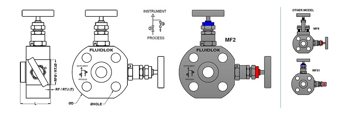
Block & Bleed Monoflange Valve - MF2
| Size | Pressure Class (lb) | Ø D | No of Holes | Ø HOLE | RF Ø | RF (T) | RTJ Ø | RTJ (T) | L |
|---|---|---|---|---|---|---|---|---|---|
| 1/2" (DN 15) | 150 | 89 | 4 | 16 | 34.9 | 1.5 | -- | -- | 51.5 |
| 1/2" (DN 15) | 300 | 95 | 4 | 16 | 34.9 | 1.5 | 50.8 | 5.56 | 51.5 |
| 1/2" (DN 15) | 600 | 95 | 4 | 16 | 34.9 | 6.4 | 50.8 | 5.56 | 56.5 |
| 1/2" (DN 15) | 900 / 1500 | 121 | 4 | 22 | 34.9 | 6.4 | 60.5 | 6.35 | 56.5 |
| 1/2" (DN 15) | 2500 | 133 | 4 | 22.2 | 34.9 | 6.4 | 65.0 | 6.35 | 56.5 |
| 3/4" (DN 20) | 150 | 99 | 4 | 16 | 43.0 | 1.5 | -- | -- | 51.5 |
| 3/4" (DN 20) | 300 | 117 | 4 | 19 | 43.0 | 1.5 | 63.5 | 6.35 | 51.5 |
| 3/4" (DN 20) | 600 | 117 | 4 | 19 | 43.0 | 6.4 | 63.5 | 6.35 | 51.5 |
| 3/4" (DN 20) | 900 / 1500 | 130 | 4 | 22 | 43.0 | 6.4 | 66.5 | 6.35 | 56.4 |
| 3/4" (DN 20) | 2500 | 140 | 4 | 22.2 | 43.0 | 6.4 | 73.2 | 6.35 | 56.4 |
| 1" (DN 25) | 150 | 108 | 4 | 16 | 50.8 | 1.5 | 63.5 | 6.35 | 51.5 |
| 1" (DN 25) | 300 | 124 | 4 | 19 | 50.8 | 1.5 | 69.9 | 6.35 | 51.5 |
| 1" (DN 25) | 600 | 124 | 4 | 19 | 50.8 | 6.4 | 69.9 | 6.35 | 56.5 |
| 1" (DN 25) | 900 / 1500 | 149 | 4 | 25 | 50.8 | 6.4 | 71.4 | 6.35 | 56.5 |
| 1" (DN 25) | 2500 | 159 | 4 | 25.4 | 50.8 | 6.4 | 82.6 | 6.35 | 56.5 |
| 1.1/2" (DN 40) | 150 | 127 | 4 | 16 | 73.0 | 1.5 | 82.6 | 6.35 | 51.5 |
| 1.1/2" (DN 40) | 300 | 156 | 4 | 22.2 | 73.0 | 1.5 | 90.4 | 6.35 | 51.5 |
| 1.1/2" (DN 40) | 600 | 156 | 4 | 22.2 | 73.0 | 6.4 | 90.4 | 6.35 | 56.4 |
| 1.1/2" (DN 40) | 900 / 1500 | 178 | 4 | 28 | 73.0 | 6.4 | 91.9 | 6.35 | 56.4 |
| 1.1/2" (DN 40) | 2500 | 203 | 4 | 31.8 | 73.0 | 6.4 | 114.3 | 7.92 | 56.4 |
| 2" (DN 50) | 150 | 152 | 4 | 19 | 92.1 | 1.5 | 101.6 | 7.92 | 51.5 |
| 2" (DN 50) | 300 | 165 | 8 | 19 | 92.1 | 1.5 | 108.0 | 7.92 | 51.5 |
| 2" (DN 50) | 600 | 165 | 8 | 19 | 92.1 | 6.4 | 108.0 | 7.92 | 56.5 |
| 2' (DN 50) | 900 / 1500 | 216 | 8 | 25 | 92.1 | 6.4 | 123.9 | 7.92 | 56.5 |
| 2" (DN 50) | 2500 | 235 | 8 | 28.5 | 92.1 | 6.4 | 133.4 | 7.92 | 56.5 |
• Dimensions are for reference only. Subject to change.
